


Stafl Systems
Insights Video Series
Learn about the latest in lithium-ion battery technology.
Erik Stafl, founder of Stafl Systems, walks you through the latest innovations in Battery Management System technology.
More videos coming soon! Stay updated by subscribing to our Youtube channel.
Proven, Reliable
Systems Engineering
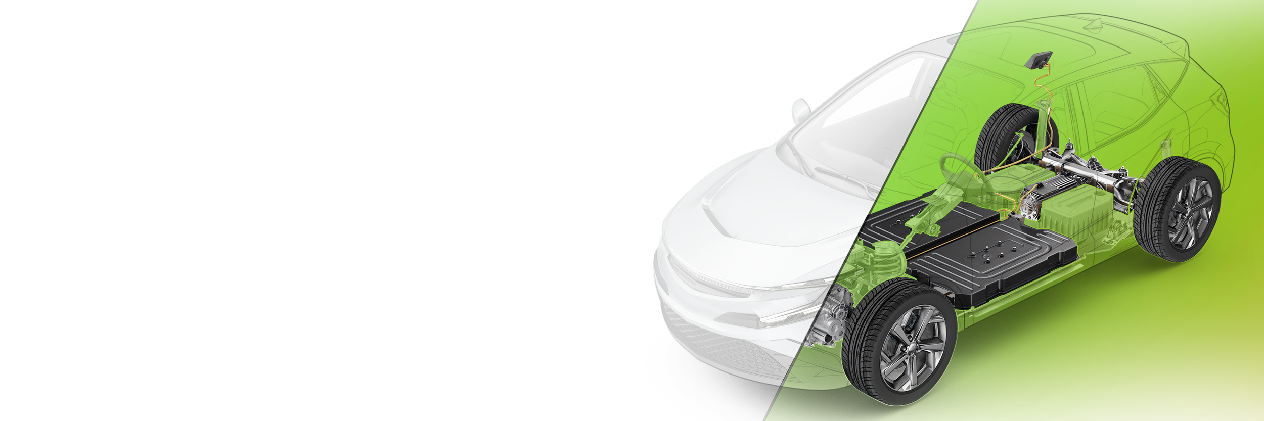
At Stafl Systems, our systems engineers work on a variety of different powertrains and vehicles to maximize performance and reliability.