
Stafl Systems
Battery Management Systems
Properly harnessing today’s most sophisticated battery technology.
Lithium-ion batteries require sophisticated management systems to control proper charging and discharging. Properly integrated into a battery pack design, Stafl Systems world-class BMS products ensure long-term, reliable operation.
BMS PRODUCT CATALOG
Stafl Systems Battery Management Systems require one BMS Master Module (e.g. BMS1000M) and 1 to 64 BMS Monitor Modules (e.g. BMS1101S / BMS1102S) to function.
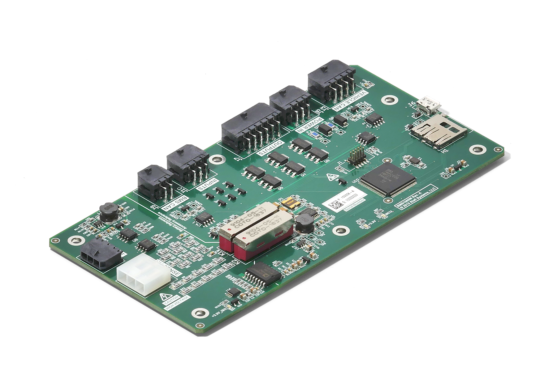
BMS1000M (BMS Master Unit)

For pricing and availability, contact us.
Integrated precharge and main contactor control circuit
Communication with Vehicle Control Unit (VCU) via standard CAN Bus Interface, with multiple supported baud rates
Standard output messages include cell voltages/temperatures, pack voltage/current, and fault flags
Runs internal balancing or commands received from VCU
May be installed externally in appropriately sealed enclosure
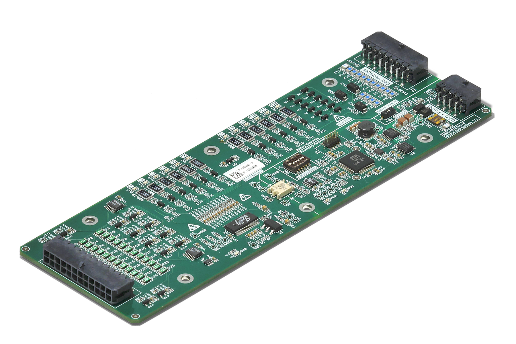
BMS1101S (BMS Monitor Unit)

For pricing and availability, contact us.
Ability to monitor and balance up to 12 series cells
Allows system to be configured for packs with 12-256 series cells
Yields excellent measurement accuracy across common pack conditions
May be installed externally in appropriately sealed enclosure
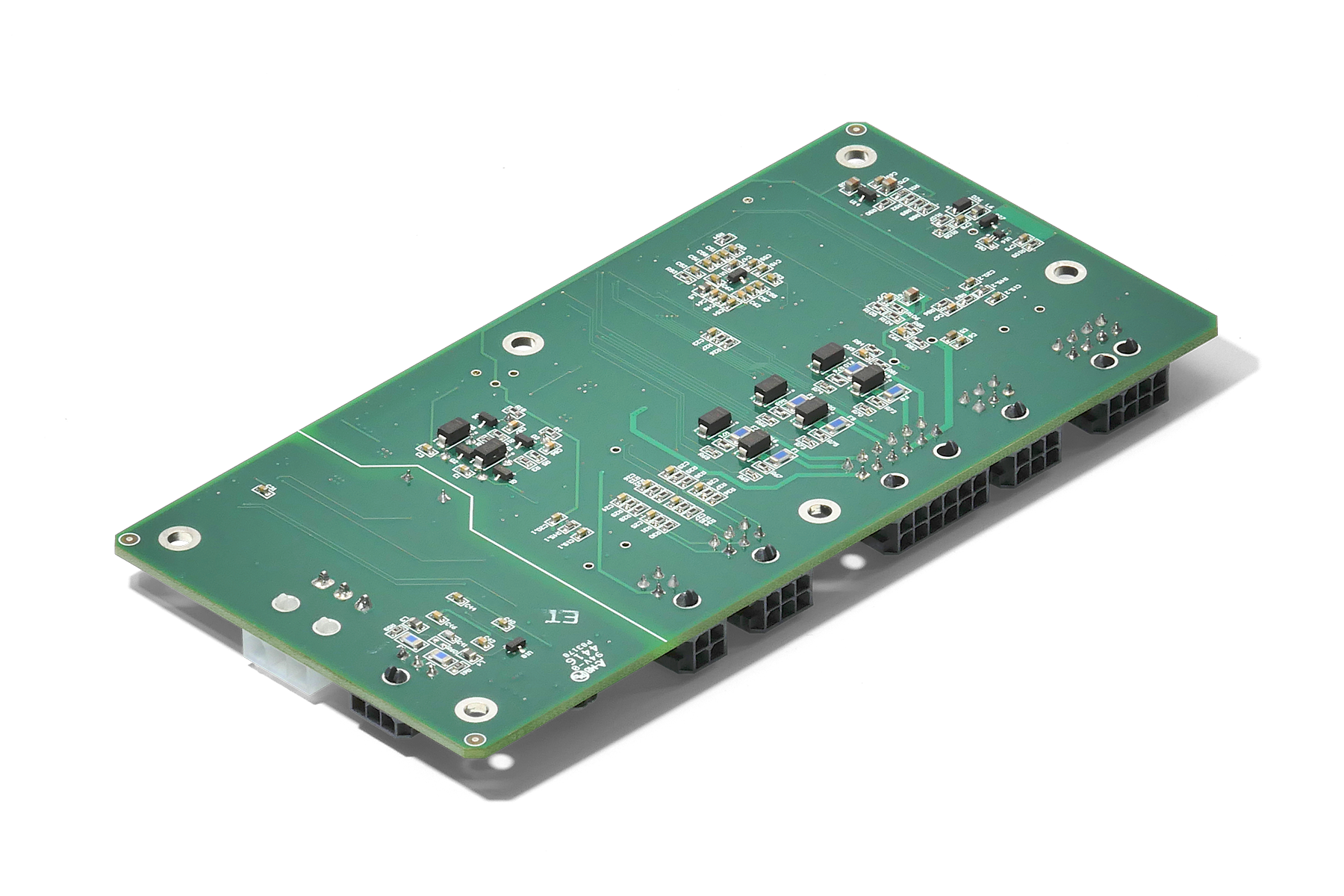
BMS1102S (BMS Monitor Unit)

For pricing and availability, contact us.
Ability to monitor and balance up to 12 series cells
Allows system to be configured for packs with 12-256 series cells
Yields excellent measurement accuracy across common pack conditions
May be installed externally in appropriately sealed enclosure


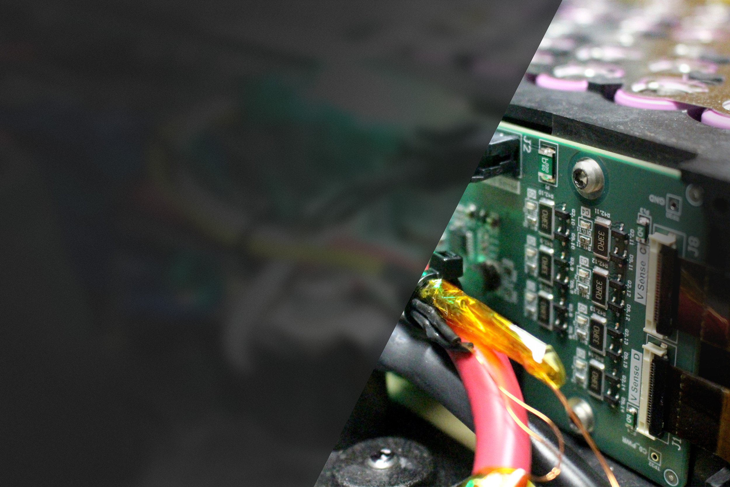
UNRIVALED ACCURACY
The Stafl Systems modular BMS1000 Series Battery Management System consists of one BMS Master Module and an application-specific number of BMS Monitor Modules.
1X Master BMS Unit
Communicates with outside system via CAN 2.0B
Manages pre-charging and contactors
Monitors pack voltages

1-64X Monitor BMS Units
Measures cell voltages and temperatures
Balances cells
Communicates with Master BMS via internal data link

precise engineering


Features
Scalable from 12 to 256 Series Cells
Temperature Sensor for Each Cell Group
Supports up to 1000V Systems
Low Steady State Cell Voltage Measurement Error (<2.0 mV)
Individual Cell Group Balancing Resistors
Externally Powered for Low Quiescent Battery Current
High Current Shunt Monitor Circuit for Accurate Pack Current Sensing
Pack Level Voltage Monitoring
Integrated Isolation Fault Monitor Circuit
SEE ALSO: BMS Product Family Brochure (PDF)
Typical System Diagram
COUNTLESS APPLICATIONS
hIGH VOLTAGE
While a vehicle’s power system sees a battery pack as a single, high-voltage battery — charging and discharging the entire battery pack at once — the battery control system must consider each battery’s condition independently.
LOW VOLTAGE
A proper system will continuously monitor important battery parameters for low voltage applications, while dealing with the varying power demands of the many aspects of operation and optimizing the usage of the battery.
stationary storage
The service life of a battery pack is tied to the weakest battery in the system. In the balancing process, each of the batteries within the string is maintained at optimal voltage levels, eliminating the ill-effects of improper charging.